Table Of Content

Communication Diagram Communication diagrams model the interactions between objects in sequence. They describe both the static structure and the dynamic behavior of a system. In many ways, a communication diagram is a simplified version of a collaboration diagram introduced in UML 2.0. The class diagram is a central modeling technique that runs through nearly all object-oriented methods.
By team
The efforts of these thinkers resulted in the release of the UML 0.9 and 0.91 documents in 1996. It soon became clear that several organizations, including Microsoft, Oracle, and IBM saw UML as critical to their own business development. They, along with many other individuals and companies, established resources that could develop a full-fledged modeling language.
Conceptual Modeling
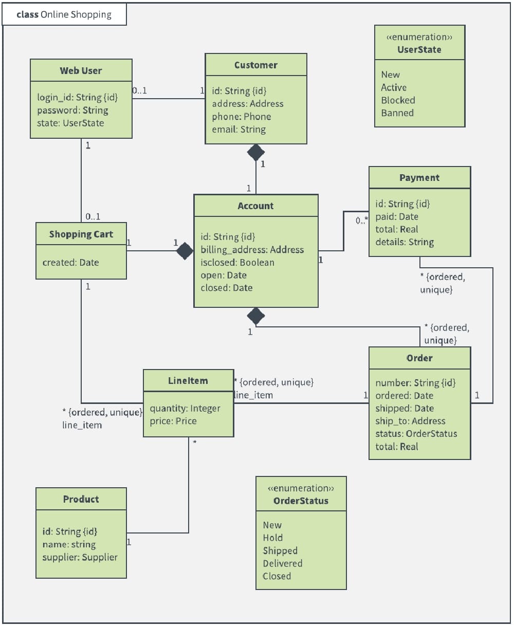
In this article, we will give you detailed ideas about what is UML, the history of UML and a description of each UML diagram type, along with UML examples. Class diagrams are a type of UML (Unified Modeling Language) diagram used in software engineering to visually represent the structure and relationships of classes in a system. UML is a standardized modeling language that helps in designing and documenting software systems. They are an integral part of the software development process, helping in both the design and documentation phases. UML is a standard language for specifying, visualizing, constructing, and documenting the artifacts of software systems.
Activity Diagram Example
Mechanical and Industrial Engineering: BUREK Lab Helps Create Sustainable and Affordable Homes Engineering ... - UMass Lowell
Mechanical and Industrial Engineering: BUREK Lab Helps Create Sustainable and Affordable Homes Engineering ....
Posted: Fri, 07 Apr 2023 21:21:32 GMT [source]
By using this diagram, they can keep track of their entire hardware mesh and prepare the system for launch without any issues. It also allows them to see performance, maintainability, and scalability. Now, let’s take a look at some of the most commonly used UML diagrams in more detail. They can also be used to update stakeholders on business operations and progress. And if you’re using a collaborative platform, you can easily invite external collaborators and stakeholders to view the diagram. Use a fishbone diagram to help you solve problems by understanding what’s causing them.
Frequently asked questions about UML diagrams
The attributes represent the characteristics or properties of the object, while the methods define the behaviors or actions that the object can perform. For example, an online shopping system could include searching, browsing, shopping, and checking out. An interaction overview diagram can account for the path customers take through all these processes. Package Diagram Package diagrams are a subset of class diagrams, but developers sometimes treat them as a separate technique. Package diagrams organize elements of a system into related groups to minimize dependencies between packages.
Create a UML diagram today
Composition is represented by a filled diamond shape on the side of the whole class. The “Library” class can be considered the source class because it contains a reference to multiple instances of the “Book” class. The “Book” class would be considered the target class because it belongs to a specific library. Start creating your first diagram today or edit one of the hundreds of free templates to get started. For more advanced features and premium templates, Lucidchart has Individual plans as low as $7.95 per month and Team plans starting at $9.00 per user per month.
4. Component Diagram
This diagram is commonly used to manage the internal structure of business processes. It allows business analysts to effectively plot and manage various workflows in one location. Because software is typically based on object-specific programming, a class diagram is probably the most commonly-used UML diagram. By using a UML diagram, you’re able to document your new software or business processes. This means you can track progress over time, make sure things are going to plan, and identify key areas of improvement. It’s a more widely used approach to application structures and modeling, as well as documenting software.

See why teams choose Lucidchart
Sequence diagrams in UML show how objects interact with each other and the order those interactions occur. It’s important to note that they show the interactions for a particular scenario. The processes are represented vertically and interactions are shown as arrows. This article explains the purpose and the basics of Sequence diagrams. Also, check out this complete Sequence Diagram Tutorial to learn more about sequence diagrams. These models capture object-oriented systems, just like class diagrams do.
Lowell by Design: A Graphic Look at Lowell History - UMass Lowell
Lowell by Design: A Graphic Look at Lowell History.
Posted: Thu, 29 Mar 2018 07:00:00 GMT [source]
Use case diagrams depict the specifications of a use case and model the functional units of a system. These diagrams help development teams understand the requirements of their system, including the role of human interaction therein and the differences between various use cases. A use case diagram might display all use cases of the system, or just one group of use cases with similar functionality. To illustrate how to create different types of UML diagrams, try one or all of these tutorials to guide you through the process of drawing both structural and behavioral diagrams. According to their website, The Object Management Group® (OMG®) is an international, open membership, not-for-profit technology standards consortium, founded in 1989.
UML is not a programming language, it is rather a visual language. The description of software architectures has always been concerned with the definition of the appropriate languages for designing the various architectural artifacts. Over the past ten years, formal or less formal Architecture Description Languages (ADLs) and supporting methods and tools have been proposed by researchers. Furthermore, the latest trends such as MDA and the aspect-oriented paradigm are tightly connected with both UML and AD, thus promoting new approaches which combine the two. This workshop attempted to delve into this multi-faceted field, by presenting the latest research advances and by facilitating discussions between experts. Simple to use drag and drop tools to easily add UML shapes onto the canvas.
UML offers many diagram types, and sometimes two diagrams can explain the same thing using different notations. It’s a great starting point for any project discussion because you can easily identify the main actors involved and the main processes of the system. You can create use case diagrams using our tool and/or get started instantly using our use case templates. A deployment diagram shows the hardware of your system and the software in that hardware.
The strength of these three approaches is utilized by the UML to represent more consistency. Before moving ahead with the concept of UML, we should first understand the basics of the conceptual model. Connect to your favorite tools with Creately plugins for Slack, Google Workspace, Confluence, and more. Advanced collaborator controls to streamline sharing, reviewing, and editing of UML diagrams. Multi-perspective modeling with adaptive shapes that change according to the context they are placed in. Lucidchart helps teams collaborate in real time from anywhere in the world.
In the aggregate, UML diagrams describe the boundary, structure, and the behavior of the system and the objects within it. Composite Structure Diagram Composite structure diagrams show the internal part of a class. Similar to Sequence Diagram, the Communication Diagram is also used to model the dynamic behavior of the use case. When compare to Sequence Diagram, the Communication Diagram is more focused on showing the collaboration of objects rather than the time sequence.
The OO design can be converted into the UML as and when required. The OO languages influence the programming world as they model real world objects. In class diagrams, parameter directionality refers to the indication of the flow of information between classes through method parameters. It helps to specify whether a parameter is an input, an output, or both. This information is crucial for understanding how data is passed between objects during method calls. Interaction overview diagrams are very similar to activity diagrams.
After the association is completed, the designing phase also gets complete. The main purpose of OO analysis is identifying the objects and describing them correctly. After the objects are identified, the designing step is easily carried out. Here the responsibility refers to the functions performed by the objects. The purpose of the system is fulfilled by collaborating these responsibilities. Universal, full-text search to easily find specific nodes and information in large, complex UML diagrams.